- #Uv 82 baofeng chirp programming install#
- #Uv 82 baofeng chirp programming mod#
- #Uv 82 baofeng chirp programming series#
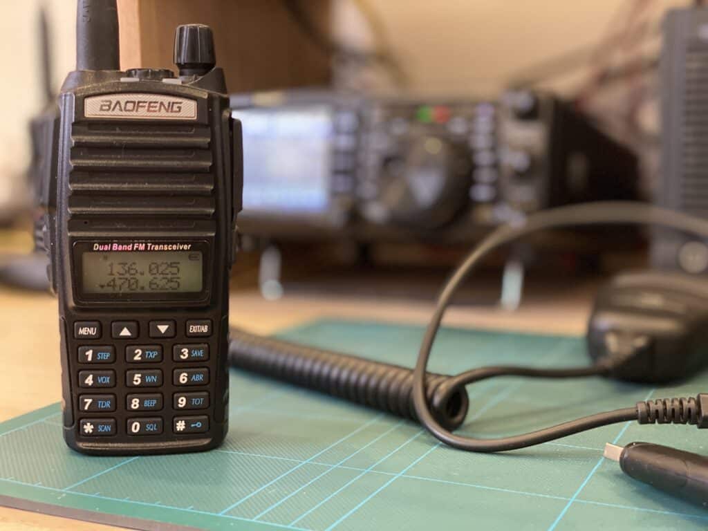
He can be reached at his QRZ email address.To anyone looking to acquire commercial radio programming software: The radio shown was modified by WB3DZZ who sells modified radios, FOBS, and other accessories.
#Uv 82 baofeng chirp programming mod#
We are planning to mod a tri-band UV5 and when we do we will do a howto on it.
#Uv 82 baofeng chirp programming series#
The Baofeng UV5 series of radios although physically different uses the same electrical connections. If you happen to have one or you acquire one it could be modified in the same way as this radio. There is a now discontinued UV-82x that is dual band 144/222. Probably the easiest place to buy is Amazon but there are other sources. Handhelds are not designed for continuous TX operation at high power. A standard unconnected stereo miniature plug can be used or preferably a plastic dummy plug cut from a stylus pen like this:Ĭut off the pen but leave the string to pull it out when needed.ĬAUTION! Do NOT run this radio on high power on a busy Allstar channel. A dummy plug should be inserted in the larger remote mic jack on the UV-82 to disable the internal microphone when using the radio as an Allstar node. It should normally be turned all the way down but you can raise it to monitor the input signal to your node. The volume on the UV82 has no bearing on Allstar levels. A good starting point is RX level = 550, and TX level = 750 but these could vary greatly depending on the FOB type you are using and the radio you are using to talk to your node. In simpleusb you would use rxboost=1, cosfrom (carrierfrom) =usbinvert, and the audio levels would need to be set. The BOTTOM display is what is received and transmitted. Once programmed you can change the channel on the radio. You also need to disable the voice prompts so they do not go out over the node. Front panel programming of a Baofeng is a chore but can be done. The easiest way to program your UV-82 is using a programming cable and Chirp. A 12V "wall wart" rated at least 2 amps would work and for portale use a larger 12V battery or car electrical system would work fine. Input voltage is about 9-24V but typically this would be run at 12-14 volts from a DC supply source. Here are photos showing the module installed in the car adapter. It has a pot to adjust the output to the 7.5 volts required for the UV-82. The replacement regulator board is available from Ebay and is very inexpensive. Here is what the adapter looks like before removing the original parts.
#Uv 82 baofeng chirp programming install#
The answer is to open the car adapter, remove the original regulator, and install an efficient replacement regulator. This quickly heats up and would destroy itself in short order. They use an inefficient three terminal regulator and an inadequate heatsink. The 12V battery eliminator adapter for the UV-82 is one way to do this but the commercial adapters are not well designed electrically. The UV-82 being a handheld is normally powered by a battery but as a node radio you would need a steady fixed source of power. It is highly recommended and often necessary that an external antenna (removed from the radio) be used to keep RF away from the radio. This is desireable as this allows the use of cosfrom=usbinvert (carrierfrom=usbinvert) in nf.Īnd here is a photo of the completed assembled radio ready to play. This results in a low going level on RX at the drain output of the 2N7000 FET. The source pin of the 2N7000 goes to ground, the drain goes to the COS pin 8, and the gate goes back to the radio to the 10K resistor.įor those wishing to see where the COS connection is in the radio here is a portion of the schematic that shows the connection.

Here is the pinout diagram of the DB25 connector. The 4.7K resistors and the 2N7000 FET are mounted at the connector end This is a view of the DB25 connector end wired to plug into a DMK/URI or similarly wire mate.

Shown here the Red is PTT, Green is RX audio, Black is TX audio, White is COS with small black on the other side of the resistor to the board, and the small black is ground. Wire colors are not important as long as you standardize at both ends. This can be a 1/4 or preferably a 1/8W resistor.

Note the COS line is fed through a 10K resistor located in the yellow heatshrink. Here are the connection points on the UV-82 circuit boardĪnd the wires after connection.


 0 kommentar(er)
